
It’s a neat thing to be able to study propagation, and to assist others in this process as well. Building the 6 meter beacon was a lot of fun, and seeing some of the reports come in are very interesting. As 10 meters continues to climb, now seems like a good time to place one on the air for 28 MHz. Here is the construction details on how I used the Radio Shack HTX-100 as a beacon transmitter. Please look at the photo gallery for close up pics, and read the picture descriptions for further construction details.
The first thing I needed to do to this radio was to remove some parts and figure out how to add the keyer and fans. I started by removing the LED that backlit the display and the speaker, since neither would be needed. The LED power source happened to be 8 volts, which worked out nicely for powering the PicoKeyer that I placed in the radio to act as the beacon keyer.
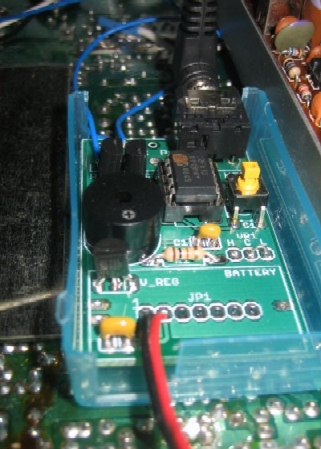
You can see the PicoKeyer installed in the area where the speaker would normally reside in the radio. The keyer was mounted in the bottom half of a pill case (I took my medicine today) with double sided tape. One of the blue wires is connected to the keying input. There is a second wire present, but only needed to connect one of them, the keyer got ground from the power connection. You can also see where I have my paddle connected to the keyer at the time of the picture…That is for programming the beacon message, keyer speed, etc.
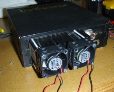
You can see the fantastic job that David Latta, KG4SNN did in mounting the fans to the back of the radio. These are two fans intended for cooling your chip in your desktop PC, and they just happen to fit nicely across the heat sink. Even nicer is that the radio chassis all ready had an areas on the back to accommodate threaded screws! The fans draw approximately 150 millamps at 12 volts, and created excellent cooling. Unfortunately, since I intend on running this transmitter from my home QTH, is created a lot more noise than I was willing to accept. I ended up finding a source for 8 volts (visible in the next photo) that I tapped and allowed the fans to run at a slower speed, create less noise and still cool the heat sinks very well.
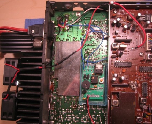
This is an overview of the bottom of the radio where I have things positioned and connected. At the time of testing on the dummy load, the radio was doing 7 watts on low power. The radio in low power mode draws less than 2 amps in transmit mode. The heat sink temperature is a consistent 90 degrees with the fans at their slow speed and was much closer to 100 degrees without any cooling.
I have three other cooling ideas that will help keep the radio cool and the lifespan of the project long. First, I’ll mount it in a temperature controlled place in the house. I also want to mount the radio heat sink up so that as much heat as possible can disapate through the fans. I have the mobile mounting bracket, and putting in on the wall in my utility area will make that an easy reality. I also realized that the sides of the case were interchangeable during the process of constructing this. So I have decided to put the side that was holding the speaker (with many holes in it) on top to allow passive cooling of final transistors. It looks a little funny, but I am sure it helps. Hope that you enjoyed hearing about this project, don’t forget to see the photo gallery for more pics.